Electromagnetic Waves in Matter

The behavior of electromagnetic waves changes dramatically when they propagate through materials rather than vacuum. This interaction between light and matter underlies numerous phenomena in our daily lives, from the colors we see to modern optical technologies. Understanding these interactions requires bridging two perspectives: the microscopic view of how individual atoms respond to electromagnetic fields, and the macroscopic description of wave propagation through bulk materials.

Microscopic Picture of Dielectric Response

Single Atom Response

To understand how materials respond to electromagnetic waves, let’s first examine how individual atoms become polarized in an electric field. Our model atom consists of:

  1. An electron charge \(-q\) uniformly distributed in a spherical cloud of radius \(a\)
  2. A positive nucleus at the center of this negative charge distribution

The charge density of the electron cloud is:

\[ \rho=\frac{-q}{\frac{4}{3}\pi a^{3}}=-\frac{3q}{4\pi a^3} \]

This configuration creates a radial electric field inside the cloud:

\[ \vec{E}(r)=-\frac{1}{4\pi\epsilon_0}\frac{q}{a^3}\vec{r} \]

where \(\vec{r}\) is the position vector from the center. The linear dependence on \(\vec{r}\) creates a restoring force similar to a spring.

Figure 1— Polarization of an electric cloud of an atom: An external electric field displaces the positive nucleus relative to the negative electron cloud, creating an induced dipole moment.

Atomic Polarizability

When we apply an external electric field \(\vec{E}_{\rm ex}\), the nucleus is displaced by a distance \(\vec{d}\) until forces balance:

\[ q\vec{E}_{\rm ex}-\frac{1}{4\pi\epsilon_0}\frac{q^2\vec{d}}{a^3}=\vec{0} \]

This force balance between the external field (pushing the nucleus) and the internal field (trying to restore the nucleus to the center) determines the atomic polarization, leading to the displacement:

\[ \vec{d}=4\pi \epsilon_0 a^3 \frac{\vec{E}_{\rm ex}}{q} \]

This displacement creates a dipole moment:

\[ \vec{p}=q\vec{d}=4\pi\epsilon_0 a^3 \vec{E}_{\rm ex} \]

The dipole moment increases linearly with the external field, with the proportionality constant:

\[ \alpha=4\pi \epsilon_0 a^3 \]

known as the electronic polarizability. Note that this polarizability scales with atomic volume.

From Single Atoms to Collective Response

When many atoms in a material are exposed to an electric field, their individual dipole moments combine to create a macroscopic polarization. The collective behavior can be characterized by the polarization density:

\[ \vec{P}=N\vec{p} \]

where \(N\) is the number of dipoles per unit volume and \(\vec{p}\) is the individual atomic dipole moment. However, this simple picture of independent atoms needs modification for dense materials where atoms are closely packed and interact with each other.

In real materials, each atom experiences not only the external field but also the fields from neighboring dipoles. This leads us to consider the local field effects and the transition from microscopic to macroscopic descriptions, which we’ll explore in the next section.

Macroscopic Description of Dielectric Materials

Polarization Density and Surface Charges

The transition from microscopic to macroscopic behavior becomes apparent when we examine a sample of polarized material. For a cylindrical sample with cross-sectional area \(A\) and height \(s\), the microscopic dipoles create observable macroscopic effects:
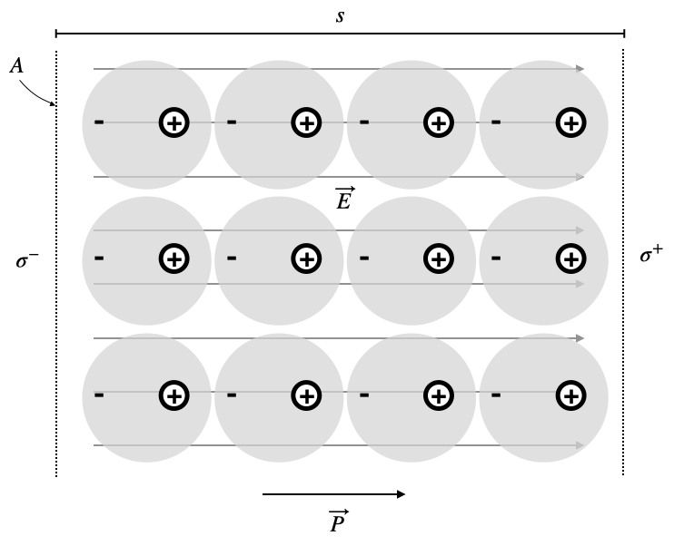
Figure 2— Polarization in a dielectric material showing aligned atomic dipoles and resulting surface charges.

This alignment leads to:

  • Total dipole moment: \(\vec{p}_{\rm cyl}=A s \vec{P}\)
  • End charges: \(q_{\rm end}=\frac{p_{\rm cyl}}{s}=A P\)
  • Surface charge density: \(\sigma=\frac{q_{\rm end}}{A}=P\)

More generally, the surface charge density at any boundary is:

\[ \sigma_b=\vec{P}\cdot\hat{n} \]

where \(\hat{n}\) is the surface normal. These surface charges are “bound” to atoms, distinct from free charges.

Volume Charge Density

When polarization isn’t uniform throughout a material, we need to consider both surface and volume charges. All bound charges in the material must sum to zero since the material was initially neutral:

\[\int \sigma_b dA +\int \rho_b dv=0\]

Using the surface charge relation \(\sigma_b=\vec{P}\cdot\hat{n}\), we can write:

\[\int \sigma_b dA = \int \vec{P}\cdot\hat{n}dA = \int \vec{P}\cdot d\vec{A}\]

Applying Gauss’s theorem:

\[\int \vec{P}\cdot d\vec{A} = \int (\nabla\cdot\vec{P})dv\]

This leads to the local relationship:

\[\rho_b = -\nabla\cdot\vec{P}\]

This fundamental equation reveals that bound volume charges appear wherever the polarization has a divergence - that is, wherever it changes spatially in a way that creates an imbalance of positive and negative charges.

Electric Displacement Field

In materials, the electric field’s divergence must account for both free charges and bound charges:

\[ \nabla \cdot \vec{E}=\frac{\rho_{\rm f}+\rho_{\rm b}}{\epsilon_0} \]

Using \(\rho_b=-\nabla\cdot \vec{P}\):

\[ \nabla \cdot \vec{E}=\frac{\rho_{\rm f}-\nabla\cdot \vec{P}}{\epsilon_0} \]

This suggests defining the electric displacement field:

\[ \vec{D}=\epsilon_0 \vec{E}+\vec{P} \]

which simplifies Gauss’s law to:

\[ \nabla \cdot \vec{D} =\rho_f \]

This is beautiful, since it brings back the same dependence on free charges as in vacuum, but now with the displacement field \(\vec{D}\) instead of the electric field \(\vec{E}\).

Linear Dielectric Response

For many materials, the polarization density is proportional to the applied electric field:

\[ \vec{P}=\epsilon_0\chi\vec{E} \]

where \(\chi\) is the electric susceptibility. This linear relationship defines linear dielectric materials, though real materials can exhibit nonlinear responses under strong fields.

The displacement field becomes:

\[ \vec{D}=\epsilon_0 \vec{E}+\vec{P}=\epsilon_0 (1+\chi)\vec{E}=\epsilon \vec{E} \]

with electric permittivity:

\[ \epsilon=\epsilon_0 (1+\chi) \tag{electric permittivity} \]

The dimensionless ratio:

\[ \epsilon_r=\frac{\epsilon}{\epsilon_0}=1+\chi \]

is the relative permittivity or dielectric constant, though it typically depends on frequency.

Clausius-Mossotti Relation

In dense materials, the local electric field \(\vec{E}_{loc}\) experienced by an atom differs from the average field \(\vec{E}\):

\[\vec{E}_{loc} = \vec{E} + \vec{E}_{dep}\]

where \(\vec{E}_{dep} = -\frac{\vec{P}}{3\epsilon_0}\) is the depolarization field from the cavity surface charges.

The polarization density relates to the local field through:

\[\vec{P} = N\alpha \vec{E}_{loc} = N\alpha(\vec{E} - \frac{\vec{P}}{3\epsilon_0})\]

Solving this equation and comparing with \(\vec{P} = \epsilon_0(\epsilon_r-1)\vec{E}\) yields the Clausius-Mossotti relation:

\[\frac{\epsilon_r-1}{\epsilon_r+2} = \frac{N\alpha}{3\epsilon_0}\]

This fundamental relation connects microscopic polarizability to macroscopic permittivity, accounting for local field effects in dense media.

Maxwell’s Equations in Matter

The presence of bound charges and currents in materials requires a modified form of Maxwell’s equations. The four fundamental equations become:

\[ \nabla \times \vec{E}=-\frac{\partial \vec{B}}{\partial t} \tag{ME.1} \]

Faraday’s law remains unchanged, describing electromagnetic induction regardless of medium.

\[ \nabla\cdot\vec{D}=\rho_f \tag{ME.2} \]

Gauss’s law now involves the displacement field \(\vec{D}\) and only free charges \(\rho_f\).

\[ \nabla\times \vec{H}=\frac{\partial \vec{D}}{\partial t}+\vec{j}_f \tag{ME.3} \]

Ampère’s law includes both the displacement current \(\frac{\partial \vec{D}}{\partial t}\) and free current density \(\vec{j}_f\).

\[ \nabla\cdot \vec{B}=0 \tag{ME.4} \]

The absence of magnetic monopoles remains fundamental. The material properties enter through the constitutive relations:

\[\begin{eqnarray} \vec{D}&=&\epsilon \vec{E}=\epsilon_0 \epsilon_r\vec{E}\\ \vec{B}&=&\mu \vec{H}=\mu_0 \mu_r\vec{H} \end{eqnarray}\]

Similar to electric polarization, materials respond to magnetic fields through magnetization \(\vec{M}\):

\[ \vec{B}=\mu_0(\vec{H}+\vec{M}) \]

For linear magnetic materials:

\[ \vec{B}=\mu_0(1+\chi_m)\vec{H} \]

where \(\chi_m\) is the magnetic susceptibility.

Wave Propagation in Non-conducting Matter

For isotropic media without free charges (\(\rho_f=0\)) and currents (\(\vec{j}_f=0\)), Maxwell’s equations lead to the wave equation:

\[ \nabla^2\vec{E}-\frac{1}{v^2} \frac{\partial^2\vec{E}}{\partial t^2}=0 \]

where the phase velocity is:

\[ v=\frac{c}{\sqrt{\epsilon_r\mu_r}} \]

For non-magnetic materials (\(\mu_r=1\)), we define the refractive index:

\[ n=\frac{c}{v}=\sqrt{\epsilon_r} \tag{refractive index} \]

This fundamental relation connects our microscopic understanding of atomic polarization to the macroscopic phenomenon of light propagation. In a later section we will provide a more detailed discussion of the microscopic origins of the refractive index. Monochromatic waves in matter take the form:

\[ \vec{E}=\vec{E}_0e^{i(\omega t- \vec{k}\cdot \vec{r})} \]

The wavevector \(\vec{k}\) relates to the vacuum wavevector \(\vec{k}_0\) through:

\[ \vec{k}=n\vec{k}_0 \]

When electromagnetic waves enter a material, their wavelength changes while the frequency remains constant. This is because:

\[ \lambda = \frac{\lambda_0}{n} \]

where \(\lambda_0\) is the vacuum wavelength. The wave frequency \(\omega\) remains unchanged:

\[ \omega = \frac{2\pi c}{\lambda_0} = \frac{2\pi v}{\lambda} \]

Special Cases

Negative Refraction

While most materials have \(n>1\), a remarkable class of engineered materials called metamaterials can exhibit negative refraction when both \(\epsilon_r<0\) and \(\mu_r<0\). In these materials:
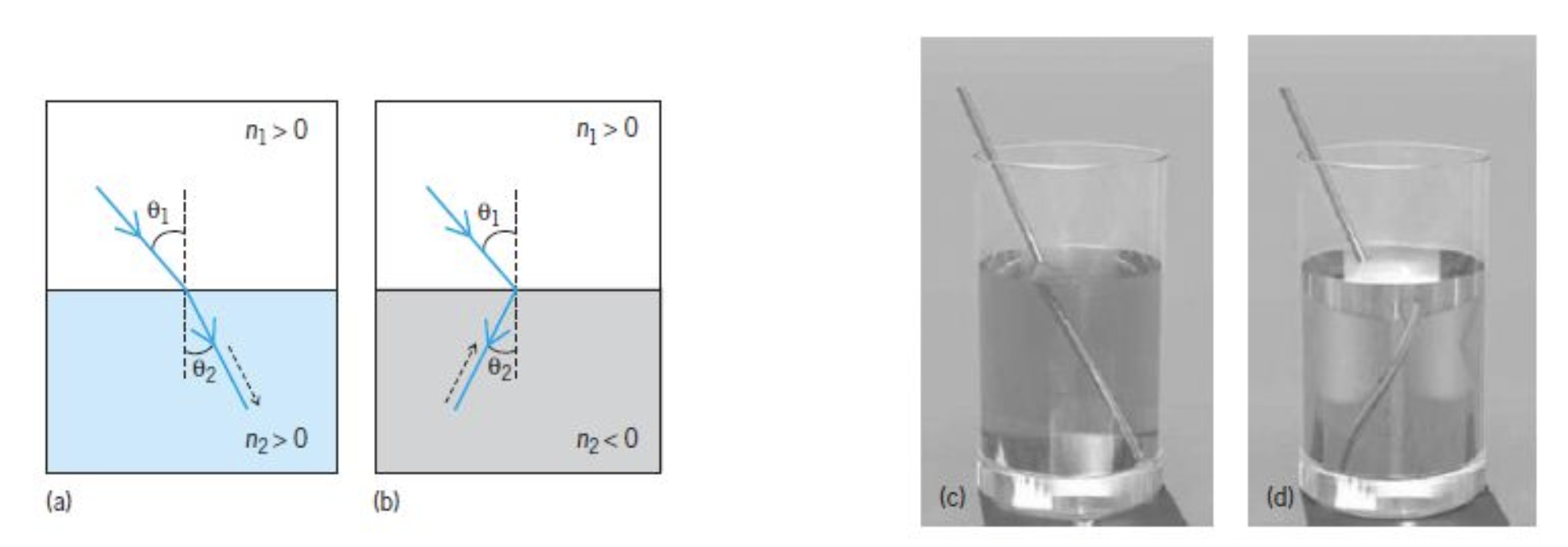
\[ v=-\frac{c}{\sqrt{\epsilon_r\mu_r}} \tag{negative refraction} \]

Figure 3— Refraction: Diagrams of (a) positive refraction and (b) negative refraction; and calculated images of a metal rod (c) in a glass filled with regular water (\(n = 1.3\)), and (d) in a glass filled with “negative-index water” (\(n = -1.3\)). In parts a and b, solid lines with arrows indicate the direction of the energy flows, broken lines with arrows show the direction of the wave vectors. (Parts c and d from G. Dolling et al., Opt. Express, 14:1842–1849, 2006).

Energy Flow in Negative Index Materials

The Poynting vector describes energy flow in electromagnetic waves:

\[ \vec{S} = \vec{E} \times \vec{H} \]

where \(\vec{H}\) relates to \(\vec{B}\) through \(\vec{B} = \mu \vec{H}\). In negative index materials, both permittivity and permeability are negative, leading to unusual behavior.

For a plane wave, \(\vec{B} = \frac{1}{\omega} \vec{k} \times \vec{E}\), giving:

\[ \vec{H} = \frac{1}{\mu \omega} \vec{k} \times \vec{E} \]

Using the vector triple product identity:

\[ \vec{S} = \frac{1}{\mu \omega} \left[ \vec{k} (\vec{E} \cdot \vec{E}) - \vec{E} (\vec{E} \cdot \vec{k}) \right] \]

Since \(\vec{E} \cdot \vec{k} = 0\) in a plane wave:

\[ \vec{S} = \frac{1}{\mu \omega} \vec{k} E_0^2 \]

In negative index materials (\(\vec{k} = -k \hat{\vec{k}}\)):

\[ \vec{S} = -\frac{k E_0^2}{\mu \omega} \hat{\vec{k}} \]

This remarkable result shows that energy flows opposite to wave propagation, a unique characteristic of negative index materials.

Metamaterial Realization
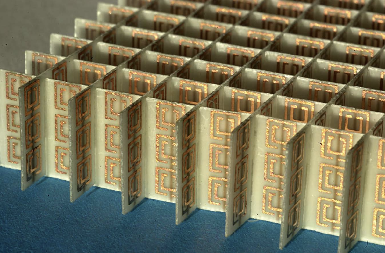
Figure 4— Metamaterial with negative refraction. Split-ring resonators provide negative permeability while metallic wires provide negative permittivity. Smith, D. R., et al. (2004). Science, 305(5685), 788-792.

A split-ring resonator typically consists of a pair of concentric metallic rings, each with a gap. These rings can be thought of as forming an LC circuit, where the rings themselves provide the inductance (\(L\)) and the gaps provide the capacitance (\(C\)).

Resonant Frequency of the SRR

The SRR behaves as an LC resonator with a specific resonant frequency (\(\omega_0\)). The resonant frequency can be expressed as:

\[ \omega_0 = \frac{1}{\sqrt{LC}} \]

where: - \(L\) is the inductance of the rings. - \(C\) is the capacitance of the gaps.

Magnetic Response of the SRR

When an external alternating magnetic field is applied perpendicular to the plane of the SRR, it induces a circulating current around the rings. This induced current creates a magnetic dipole moment that opposes the change in the external magnetic field (Lenz’s Law).

Magnetic Susceptibility

The magnetic susceptibility (\(\chi_m\)) of the SRR can be related to the magnetic moment (\(m\)) induced in response to the external magnetic field (\(H\)):

\[ m = \alpha H \]

where \(\alpha\) is the polarizability of the SRR. The susceptibility is given by:

\[ \chi_m = \frac{m}{H} = \alpha \]

Polarizability of the SRR

The polarizability \(\alpha\) can be modeled using the Lorentz oscillator model for the resonant behavior of the SRR. This gives:

\[ \alpha(\omega) = \frac{F\omega^2}{\omega_0^2 - \omega^2 - i\gamma\omega} \]

where: - \(F\) is a geometric factor related to the SRR. - \(\omega_0\) is the resonant frequency. - \(\gamma\) is the damping factor (related to losses). - \(\omega\) is the angular frequency of the applied magnetic field.

Effective Permeability

The effective permeability \(\mu(\omega)\) of the metamaterial containing SRRs can be expressed in terms of the magnetic susceptibility \(\chi_m(\omega)\):

\[ \mu(\omega) = 1 + \chi_m(\omega) \]

Substituting \(\chi_m(\omega)\) with \(\alpha(\omega)\):

\[ \mu(\omega) = 1 + \frac{F\omega^2}{\omega_0^2 - \omega^2 - i\gamma\omega} \]

This equation describes the frequency-dependent effective permeability of a metamaterial containing split-ring resonators.

Negative Permeability

For negative permeability to occur, the term in the denominator \((\omega_0^2 - \omega^2 - i\gamma\omega)\) must be such that the real part of the permeability becomes negative. This generally happens in the frequency range around the resonant frequency \(\omega_0\). Specifically, when \(\omega\) is slightly below \(\omega_0\), the real part of \(\mu(\omega)\) can become negative due to the resonance.

The final equation for the effective permeability of a metamaterial with split-ring resonators is:

\[ \mu(\omega) = 1 + \frac{F\omega^2}{\omega_0^2 - \omega^2 - i\gamma\omega} \]

Interpretation

  • When \(\omega\) is near \(\omega_0\), the permeability \(\mu(\omega)\) can exhibit negative values.
  • The parameters \(F\), \(\omega_0\), and \(\gamma\) are determined by the geometry and material properties of the SRRs.

This equation highlights how the resonant properties of the SRRs lead to a negative permeability in the metamaterial, enabling unique electromagnetic properties such as a negative refractive index.

The concept of negative refractive index, first theorized by Victor Veselago in 1968, predicted materials with simultaneous negative permittivity and permeability would exhibit:

  • Reversed Snell’s law
  • Reversed Doppler effect
  • Reversed Cherenkov radiation

Modern realizations use carefully designed structures with:

  • Split-ring resonators for negative μ
  • Wire arrays for negative ε
  • Precise geometric arrangements to maintain wave propagation

These materials enable novel applications including:

  • Superlenses breaking the diffraction limit
  • Electromagnetic cloaking
  • Novel waveguiding devices

The concept of negative refractive index was first theorized by Veselago (Veselago 1968). Later, Pendry showed how these materials could be used to create perfect lenses (Pendry 2000).

References

Pendry, John B. 2000. “Negative Refraction Makes a Perfect Lens.” Physical Review Letters 85 (18): 3966–69.
Veselago, Victor Georgievich. 1968. “The Electrodynamics of Substances with Simultaneously Negative Values of \(\epsilon\) and \(\mu\).” Soviet Physics Uspekhi 10 (4): 509–14.